Radiated susceptibility
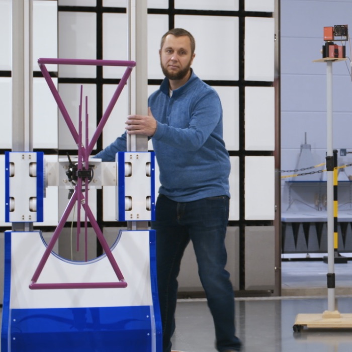
A comparison between an old FM radio antenna on a car (100 MHz range) and an antenna on a Wi-Fi router (2.4 GHz) shows that the higher the frequency, the smaller the antenna needs to be for reception.
At sufficiently high frequencies, the conductor tracks and internal connection cables of your device become a receiving antenna for interference energy. A simple test you can do at home shows this effect: place your cell phone on top of a loudspeaker and call that phone; you will hear a crackling sound in the speaker, caused by the transmitting power of your cell phone.
Depending on the area of application, considerable field strengths can affect your device, from 200 V/m (in the area of radar systems) up to several gigahertz. A conductor through which a current flows always also generates a magnetic field in its surroundings. If this conductor is wound into a coil, a higher number of turns also increases the magnetic field that is created. This explains why strong magnetic fields (of up to 300 A/m) are always present in the vicinity of large power consumers.
The standards and procedures in this area include the following:
- IEC 61000-4-3 – High-frequency EM fields
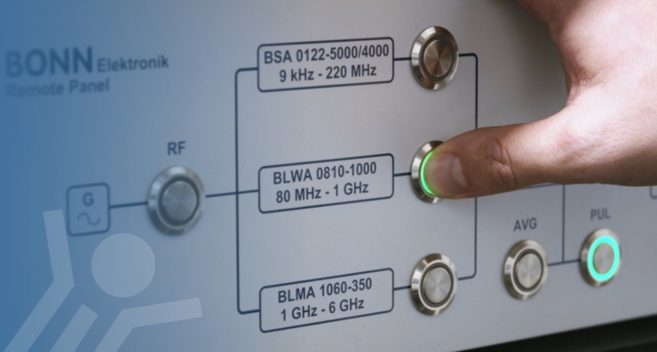
The purpose of this test is to determine, under reproducible conditions, whether a test object functions satisfactorily when exposed to high-frequency electromagnetic fields from any source such as radio transmitters, cell phones or unintentional fields from nearby devices. In recent years, there has been a significant increase in the use of radiotelephones and other RF users operating at frequencies between 0.8 GHz and 6 GHz. In addition to the electromagnetic fields that are functionally required and thus deliberately generated, there are electromagnetic radiations caused by devices such as welding equipment, fluorescent lamps or when switching inductive loads (motors).
The term "field strength" may only be used for measurements in the far field (distance > 1 x wavelength). Either the electric or the magnetic component of the field can be measured, and the measurement result can be expressed in V/m or A/m; each of these units of measurement can be converted into the other.
For measurements in the near field (distance < 1 x wavelength), the terms "electric field strength" or "magnetic field strength" are used because the relationship between the two values is complex and difficult to measure. Powerful RF amplifiers with a power of several hundred watts are required to generate these field strengths. If the available power of these amplifiers is not sufficient to produce the required field strength at a distance of 3 m, testing may be carried out using the independent windows method at a shorter distance of 1 m for frequencies above 1 GHz (the wavelength for 1 GHz corresponds to 30 cm).
During the test, disturbing signals are modulated using appropriate RF modulation techniques, usually amplitude modulation with a modulation depth of 80 % and a modulation frequency of 1 kHz. In this process, the 80 % modulation depth for amplitude modulation describes that the amplitude varies with the modulation frequency between 1.8-fold and 0.2-fold. At a test value of 10 V/m, peak values of 18 V/m are generated.
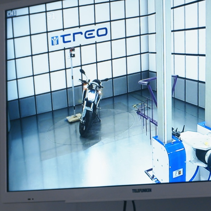
Other common modulation types are pulse modulation or frequency modulation. Since the field strengths generated during the test interfere with the general radio spectrum (for example radio transmitters) and in order to protect persons in the vicinity, such tests must only be performed in enclosed shielded rooms.
- IEC 61000-4-9 – Pulsed magnetic fields
Pulsed magnetic fields mainly occur in industrial plants, power stations, railway systems and medium-voltage and high-voltage switchgear. This test method does not deal with capacitive or inductive coupling into lines as does for example IEC 61000-4-5.
The high currents of a surge propagating on a cable generate corresponding magnetic fields of considerable magnitude up to one thousand A/m in their immediate vicinity. These pulses are simulated by means of an induction coil, in the center of which the test object is placed. If the test object cannot be enclosed by the standard induction coils, either the approximation method or a non-standard induction coil can be used. Special attention should hereby be paid to the curve shape of the surge.
- RTCA/DO-160 Sec 21.5 – Emission of Radio Frequency Energy
This method is very similar to the test according to MIL-STD-461 RE102. However, in this case the test object is placed directly in front of the antenna even at low frequencies, whereas with RE102 this is only the case starting from 200 MHz (however, section 21.5 only starts at 100 MHz). In addition, the empty field calibration power similar to IEC 61000-4-3 is used as the controlled variable. The RTCA usually tests in at least 2 modulations, either "continuous wave" or unmodulated, and "square wave”, which is a pulse modulation with a 50 % modulation depth.
- MIL-STD-461 RS103 – Radiated Susceptibility, Electric Field
This requirement serves to prove the functionality of the test object in high-frequency electrical fields. In contrast to IEC 61000-4-3, the real field strength on the test object is used as the controlled variable, not the forward power previously determined in the test volume. In addition, a pulse modulation with a 50 % depth and a frequency of 1 kHz is used as modulation. With pulse modulation, the disturbing signal has a rectangular envelope; the 50 % refers to the ratio of switched-on to switched-off state.


Head of EMC Laboratory
Carsten Möller
B. Sc.
Testing? Treo
EMC testing areas:


